Project:
Building a 9/16" by 30 TPI threading die for a local bag pipe shop
Difficulty Level (Easy, Medium, Hard, Insane):
Medium
Process:
A local bag pipe shop owner called me a couple of days ago asking if I could make him a custom die so he can thread some stock delrin with a 9/16" by 30 TPI male thread. After some research I found that a 30 TPI is a virtually non-existent pitch so there was no dies available that I could find.
I did find a matching tap but it was over $80 bucks. When I planned out how to make this die I figured if I can thread a piece of O1 tool steel to the proper size, I could mill some relief angles to make the cutting edges, harden and sharpen it and then use this custom tap to cut the inside threads of a piece of 4140 steel. Once that was tapped I would heat, quench and temper the final die so that's what I set out to do.
Unfortunately, after several hours when I had finally completed the tap I used my belt sander to cut some relief angle into the tap just to realize when I was done that I had done so at the wrong side and essentially dulled the tap beyond any use.
After I got over the disappointment, I figured I could use the
Threading Insert Tool Holder that I had used to make the
Milling Head Ejector Nut and skip the tap altogether.
After cutting off a 1/2" piece of 4140 on my fixed
Metal Band Saw, I chucked it up, faced both sides, drilled and bored it to size and then used my
39 Tooth Gear to enable my lathe to cut 30 TPI threads.
After the bored piece was tapered on one side to make it easier to start the tap I cut the internal threads which actually worked out quite well.
Once the threads were cut, I mounted my
DIY Dividing Head, set my mill to the horizontal position and drilled 6 equally spaced relief holes.
All I had to do now was heat the die with my
Propane Burner, quench and temper the die, then do a final sharpening of the cutting edges as well as some cosmetic clean up and engrave the size and TPI values on the die.
Pictures:
 |
| The bag pipe piece the final threaded piece should fit into |
 |
| Another view of the piece with the female thread |
 |
| A piece of delrin |
 |
| The 1/2" piece of 4140 I cut up to make the die out of |
 |
| A 3" piece of 3/4" O1 tool steel to make the tap out of |
 |
| The chart showing how to enable a 30 TPI thread on my lathe |
 |
| Facing the O1 tool steel |
 |
| After the O1 tool steel was threaded and tapered |
 |
| Setting up my dividing head |
 |
| Cutting some relief into the tap |
 |
| The finished cutting end of the tap |
 |
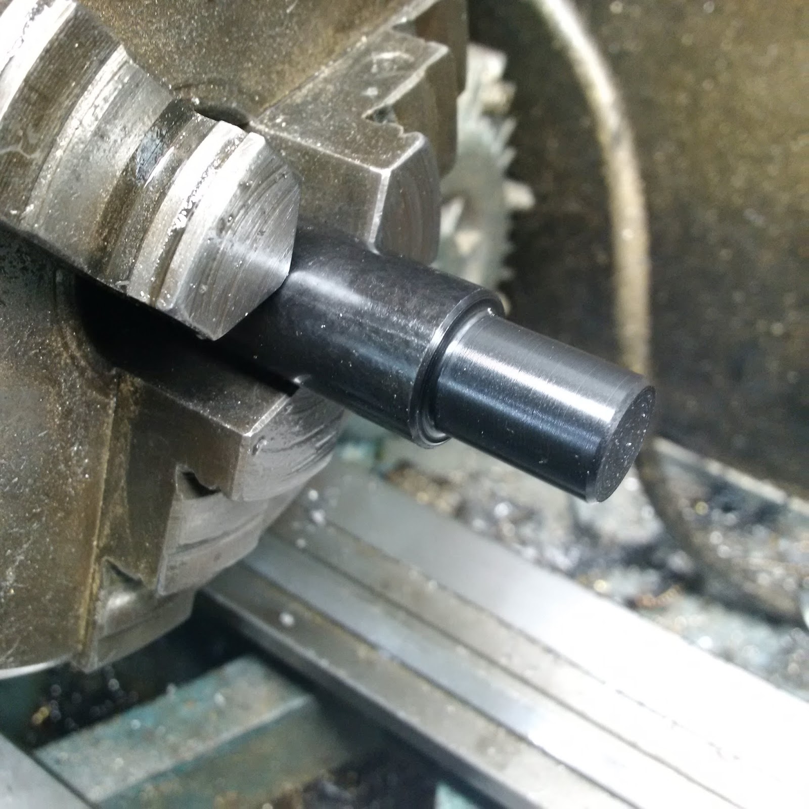
| Turning the shank down to 1/2" |
 |
| The finished tap |
 |
| Another view |
 |
| Heating the tap |
 |
| The glowing red hot tap |
 |
| Quenching the tap in some old motor oil |
 |
| A layer of oil smoke in my shop. I thought it looked kind of cool |
 |
| The hardened tap |
 |
| Drilling the die blank |
 |
| Mounting it on an arbor to turn the outside to a bit under 1" |
 |
| Boring the die |
 |
| Another view |
 |
| Threading the inside of the die |
 |
| Using the tap to clean up the inside thread |
 |
| Another view |
 |
| Drilling some recesses to hold the die in the die holder with the set screws |
 |
| The die mounted in the die holder on the tap in the vise |
 |
| Another view |
 |
| After the relief holes were cut; I did not have enough material along the insides and the cutting edges were too wide |
 |
| Another view of the (first version) finished die |
 |
| Another view |
 |
| Turning the delrin to 9/16" |
 |
| The new (first version) die in the holder |
 |
| Close-up of the delrin turned to 9/16" |
 |
| The inferior threads left with the first version die |
 |
| Threading the second version die blank |
 |
| The threaded die |
 |
| Fitting a test piece on the die |
 |
| Getting ready to drill the relief holes |
 |
| Closeup of the setup |
 |
| Testing how 8 relief holes would work out. I ended up deciding against it |
 |
| Six relief holes looked better so I went with that |
 |
| Cutting the first relief hole |
 |
| After all the holes were cut |
 |
| The finished, non-hardened (second version) die |
 |
| Getting ready to heat the die |
 |
| The glowing die just before quenching it |
 |
| The hardened die |
 |
| After I cleaned it up on the belt sander |
 |
| Engraving the die size with a diamond tipped dremel bit |
 |
| The completed 9/16" - 30 TPI die |
Tools:
Lathe and accessories
Threading Insert Tool Holder
Metal Band Saw
39 Tooth Gear
DIY Dividing Head
Propane Burner
Dremel
Belt sander
Tap & die set
Materials:
3" of 3/4" O1 tool steel
Two 1/2" pieces of 1-1/4" metal (4140)
Cost:
$0.00
Time:
7 hrs
Savings:
$80.00
Conclusion:
It works and looks really nice. I'm amazed how many uses for my lathe I have discovered since I got it last summer.